
ТЕХДОКУМЕНТАЦИЯ > LILIN
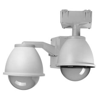
OUTDOOR HOUSING
PIH - 510 H/L/G & 510 H/L/G IP
INSTALLION / OPERATION MANUAL
INSTALLATION
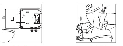
Step 1 Separate The Housing and PSU Box
.jpg)
|
Untighten the screws from PSU box |
Untighten and pull out the bolt from the hinge |
Separate the housing and PSU box |
Untighten the screws from PSU box and open it. (Goose Neck) |
Step 2 Install Power Supply Unit
When use 24Vac power source:
.jpg)
|
Put the PSU into the Box |
Tighten 2 screws to fix the PSU |
When use 90~260Vac power source:
.jpg)
|
Put PSU into the box |
Put the clamp on PSU |
Tighten 2 screws to fix the PSU |
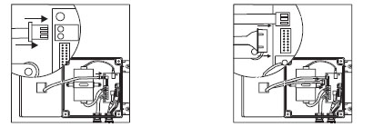
Step 3 Install the Power Box
.jpg)
|
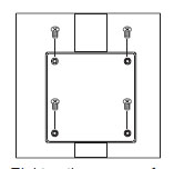
Drill 4 holes on desired locations |
Tighten 4 screws to fix the power box (These four screws are not supplied. User must prepare their own screws.) |
Drill holes on the intended positions of of the wall. (Goose Neck) |
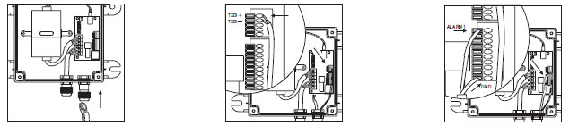
Step 4 Connection
Outdoor Housing Connection
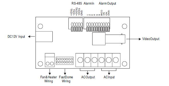
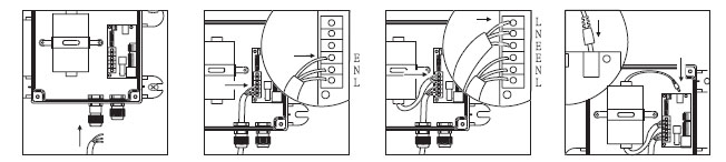
1. Connect AC / DC cables:
.jpg)
|
Untighten the left knob, put the AC power cable through the hole and tighten the knob |
Connect the AC power cable to AC Input jack |
Connect the AC power cable(below) to AC Output jack |
Connect the DC power cable(above) to DC Input jack |
2. Connect Alarm, telemetry control (RS-485) and Video cables:
.jpg)
|
Untighten the right knob, put the Alarm, RS-485 and video cables through the hole and tighten the knob |
Connect the telemetry control (RS-485) to RS-485 Input (TXDI+,TXDI-) |
Connect the Alarm input cable to Alarm Input (Alarm 1 & GND) |
Connect the video cable to output jack |
Outdoor Housing for IP Series Connection
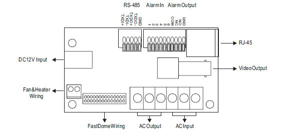
1. Connect AC / DC cables:
|
Untighten the left knob, put the AC power cable through the hole and tighten the knob |
Connect the AC power cable to AC Input jack |
Connect the AC power cable(below) to AC Output jack |
Connect the DC power cable(above) to DC Input jack |
2. Connect Alarm, RS-485, RJ-45 and Video cables:
|
Untighten the right knob, put the Alarm, RS-485, RJ-45 and video cables through the hole and tighten the knob |
Connect the telemetry control (RS-485) to RS-485 Input (TXDI+,TXDI-) |
Connect the Alarm input cable to Alarm Input (Alarm 1 & GND) |
|
Connect the network cable to RJ-45 jack |
Connect the video cable to output jack |
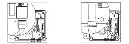
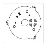
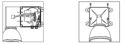
Step 5 Attach the Base to Housing
|
Turn the dome cover anti-clockwise |
Separate the dome cover from camera |
Untighten the 3 screws from base |
|
Turn the camera body anti-clockwise |
Separate the camera body and base |
Unplug the connection cable |
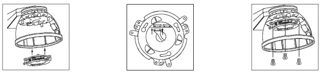
|
Attach the base to housing |
Connect the housing cable |
Tighten 3 screws to fix base |
Step 6 Camera Setting
Setting Fast Dome ID
Setting Alarm Mode
Setting Camera Function
Setting Fan Power
Refer to FastDome operation manual for camera setting
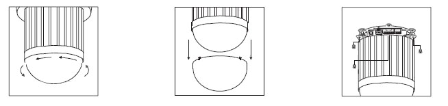
Step 7 Attach Camera Body and Base
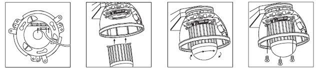
|
Reconnect the connection cable |
Attach camera body to base |
Turn camera body clockwise to high position |
Tighten the three screws to fix the camera body |
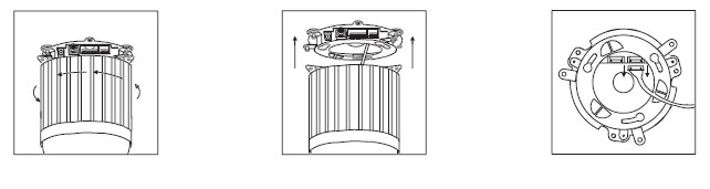
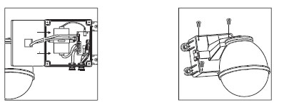
Step 8 Install The Dome Cover and Housing Cover
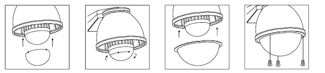
|
Attach the dome cover to camera |
Turn the dome cover clockwise to tight position |
Attach the cover to housing |
Tighten the 3 screws to fix the cover |
Step 9 Attach PSU and Bracket
|
Attach the housing back to PSU box |
Insert the bolt into the hinge and tighten |
|
Connect the fan & heater cable to pin jack |
Connect the Fast Dome cable to connection jack |
Step 11 Install the Power Box, Bracket and Housing
Pendant
|
Attach the bracket and housing to the box |
Tighten the 4 screws to fix the bracket |
Wall Mounting
|
Attach the bracket and housing to the box |
Tighten the 4 screws to fix the bracket |
Swan Neck
Tighten the screws of
PSU box to fix the cover.
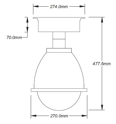
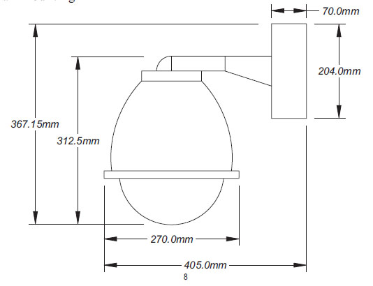
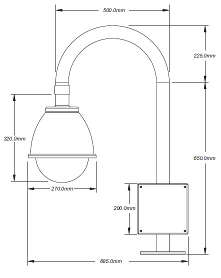
STRUCTURAL DRAWING
Pendant
Wall Mounting
Swan Neck
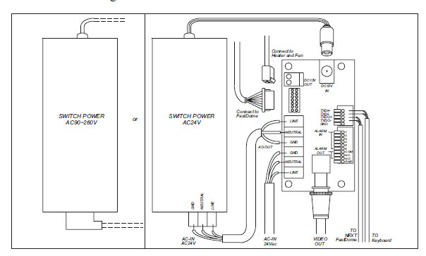
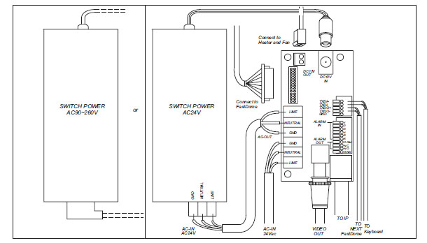
WIRING DIAGRAM
Outdoor Housing
Outdoor Housing for IP Series
SPECIFICATION
Outdoor Housing
|
Model No. |
PIH-510 H |
PIH-510 L |
PIH-510 G |
|
|
Type |
Pendant |
Wall Mounting |
Swan Neck |
|
|
Construction |
Brocket |
Aluminum |
||
|
Top |
Flame Resistant ABS |
|||
|
Internal Fixing |
Steel |
|||
|
Housing |
Polycarbonate |
|||
|
Connection PCB |
Input Voltage |
DC12V |
||
|
Current Consumption |
700mA (Fan + Heater) |
|||
|
RS-485 |
RS-485 In (2 inputs) RS-485 Out (2 outputs) |
|||
|
Alarm |
Alarm-In (6 inputs) Alarm-Out (3 outputs) |
|||
|
Heater Activation |
On +15 C OFF +25 C |
|||
|
Fan Activation |
On +35 C OFF +25 C |
|||
|
Dimension |
270mm(_) x 297.5mm(H) |
|||
|
Weight |
4.8Kg |
5Kg |
10Kg |
|
Outdoor Housing for IP Series
|
Model No. |
PIH-510 H |
PIH-510 L |
PIH-510 G |
|
|
Type |
Pendant |
Wall Mounting |
Swan Neck |
|
|
Construction |
Brocket |
Aluminum |
||
|
Top |
Flame Resistant ABS |
|||
|
Internal Fixing |
Steel |
|||
|
Housing |
Polycarbonate |
|||
|
Connection PCB |
Input Voltage |
DC12V |
||
|
Current Consumption |
700mA (Fan + Heater) |
|||
|
RS-485 |
RS-485 In (2 inputs) RS-485 Out (2 outputs) |
|||
|
RJ-45 |
One RJ-45 for Ethernet (10 Base-T) |
|||
|
Alarm |
Alarm-In (6 inputs) Alarm-Out (3 outputs) |
|||
|
Heater Activation |
On +15 C OFF +25 C |
|||
|
Fan Activation |
On +35 C OFF +25 C |
|||
|
Dimension |
270mm(_) x 297.5mm(H) |
|||
|
Weight |
4.8Kg |
5Kg |
10Kg |
|